
What is a Potential transformer?
 The primary and secondary windings of the transformer are wounded around the core, so this type transformer is also called wound type potential transformer. This potential transformer is shell type or core type and these transformers do not use any electronic component for reducing the secondary voltage such as a capacitor.

The magnetic transformer again reduced the high voltage to low voltage with high accuracy which can be measured by the voltmeter or wattmeter. Capacitive voltage transformers are used for high voltage power transmission lines.
 The capacitive potential divider converts the extra high voltage into the lower voltage. This lower voltage is again converted into the lower voltage by a magnetic transformer which can easily be measured by a voltmeter. The output of the capacitive potential divider works as input for the magnetic potential transformer.
A potential transformer is an instrument transformer that is used to step down the higher-level voltage to lower-level voltage that can easily be measured with help of instruments like a voltmeter, Wattmeter and watt-hour meter.
The potential transformers are accurate ratio step down transformers. The potential transformer has low power rating windings.

The potential transformer consists of primary windings with a large number of turns of copper wire and secondary winding consists of less number of turns which is rated for 110V.
The primary winding is connected to the high voltage transmission line which voltage can be measured and secondary windings are connected to the low range voltameter coil. One end of the secondary winding is always earthed for safety purposes. to prevent secondary winding from reaching dangerous potential, the end secondary winding of the potential transformer is earthed.
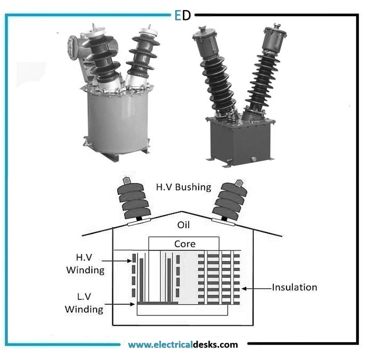
Construction of potential transformer:
Various parts of the potential transformer are
1. Core
2. Windings
3. Insulation
4. Bushings
1. Core:
The core of a potential transformer may be shell type or core type. In core type potential transformer, windings surrounding the core. In a shell-type potential transformer, the core surrounding the windings. The shell type potential transformer is used for low voltage uses and the core type transformer is used for high voltage uses.
The potential transformer is used a larger core and a larger conductor size compared to the conventional power transformer. At the time of assembly special core is required to reduce the effect of the air gap at the joints.
The core of the potential transformer is made from high-quality silicon steel material which has low flux density so that magnetising current remains small.
2. Windings
The coaxial primary and secondary windings are used in potential transformers for reducing the leakage reactance. In a potential transformer, the secondary winding is low voltage winding which is placed next to the core.
The primary winding is single coil winding in a low voltage transformer. For high voltage transformer, insulation between the core and windings and between each winding is the main problem.
For high voltage potential transformers, the primary winding is divided into a number of small sections of short coils to reduce the need for insulation between the coil layers.
The terminal of the potential transformer is so designed that variation of the voltage ratio the load remain minimum. The phase shift between the input and output also remains minimum.
The primary windings consist of a larger number of turns and the secondary windings consist of a small number of turns which is rated at 110V.
3. Insulation
The cotton tape and varnished cambric are used as insulation for primary and secondary windings. Between the primary and secondary coils, hard fibre separators are used. In a high voltage transformer oil is used as the insulating medium. The oil-immersed potential transformer is used for voltage levels above 7kV. The potential transformer having a ratting more than 45KVA uses porcelain material as an insulator.
4. Bushings
For oil-filled transformers, oil-filled porcelain bushings are used. The bushings are insulating devices through which the transformer is connected to the external circuit. The bushings are made from porcelain material.
There are two porcelain bushings are used when no side of the line is at earth potential. The potential transformer is used oil as an insulating medium which is used oil-filled bushings. A potential transformer that connects to the ground neutral uses only one high voltage porcelain windings.
Working of Potential transformer:
The working of the potential transformer is similar to the conventional power transformer. The electrical power is transferred from primary to secondary windings through electromagnetic induction.
The alternating voltage at primary windings generates alternating magnetic flux in the transformer core. The primary and secondary windings of potential transformer are wound in the same magnetic core. So this alternating flux generates a voltage in secondary windings. The secondary windings consist of lower turns than the primary windings, so voltage induced in the secondary windings is smaller.
The secondary voltage can be easily measured by using a voltmeter, wattmeter. The potential transformer has a very high impedance. The current flowing through the secondary of the potential transformer is very low, so the potential transformer has very low VA ratings around 200VA.
Types of Potential transformer
1. Electromagnetic potential transformer
2. Capacitive potential transformer
1. Electromagnetic potential transformer:
The potential transformer uses the electromagnetic induction principle to convert high voltage to low voltage is called an electromagnetic potential transformer.
The main problem in an electromagnetic transformer is the insulation problem for high voltages. Due to insulation problems in potential transformer for higher voltages above 10kv design become very complex. The electromagnetic transformers are very expensive because of more insulation requirements.
2. Capacitive potential transformer:
The Capacitive potential transformer is a combination of capacitance potential divider and magnetic potential transformer with a small transformation ratio. The capacitor voltage divider is used to lower down the very high voltage to below the 10kV. The capacitors are connected in series on the primary side of the magnetic transformer.
The capacitive potential dividers, inductive elements and magnetic transformer are three main parts of a potential transformer.
For measuring high voltages above 100Kv high insulated potential transformer is required. The highly insulated potential transformer has more cost due to more insulation required. The capacitive transformer is cheap because less insulation is required. For reducing the cost, a capacitive voltage transformer is used for higher voltages.
In potential divider consists of two capacitances C1 and C2. One capacitance C1 is placed near the high voltage transmission line and the other capacitance C2 is placed near the ground.
The capacitance C1 which is near to the transmission line has lower capacitance and capacitance C2 which is near to the ground has Higher capacitance.
The meter used for measurement of Low voltage is resistive and the capacitive potential divider is capacitive. So phase shift occurs and output will be affected. This problem can be overcome by placing inductance in series with the magnetic transformer.
The capacitive voltage transformer is free from the burden. The burden is nothing but the load on the secondary winding of the potential transformer.
Advantages of Potential transformer:
1. The capacitive potential transformer is used for measurement of higher voltages.
2. The potential transformer enables the ordinary voltmeter to measure very high voltages.
3. The potential transformer offers electrical isolation between voltameter and very high voltage power lines.
Disadvantages of Potential transformer:
1. The Potential transformer can only measure AC voltage. It can not measure DC voltage.
2. The potential transformer is more expensive than the ordinary transformer.
Applications of Potential transformer:
1. The potential transformer is used for the metering purpose.
2. The potential transformer is used for protection of feeders.
3. The potential transformer is used for protecting the impedance of generators.
4. The potential transformer is used for synchronising the generators and feeders.
5. The potential transformer is used for monitoring the industrial load.
6. The potential transformer is used for power line carrier communication networks.
7. The potential transformer are used for measuring the higher voltages.
8. The potential transformer is used for operating protective relays.