
Transmission Line classifies into two types:
1. AC Transmission Line
2. DC Transmission Line
1. AC Transmission Line:
An AC transmission line is a set of conductors that are used to transmit electrical power from a generating station to load centers over long distances. These lines are made up of three main components: resistance, inductance, and capacitance. These components are distributed uniformly along the entire length of the line.
Resistance is the opposition to the flow of electric current in a conductor, and it is caused by the collisions between the electrons and the atoms in the conductor. The resistance of the transmission line is caused by the resistance of the conductors and the resistance of the connections between the conductors.
Inductance is the property of a conductor by which it resists any change in the current flowing through it. When the current flowing through the transmission line changes, it induces an electromotive force (EMF) in the line, which opposes the change in current. This opposition to change in current is known as inductive reactance.
Capacitance is the property of a conductor by which it stores electric charge. The capacitance of the transmission line is caused by the presence of two conductors carrying current, separated by an insulator. The capacitance acts as a shunt element along the length of the transmission line.
Based on the operating voltage and length, the overhead AC transmission lines are classified into three types:
- Short transmission lines
- Medium transmission lines
- Long transmission lines
1. Short Transmission Line:
Short transmission lines are overhead power lines that are used to transmit electrical power over a distance of less than 50 km. These lines are typically used to distribute power from a substation to the load centers in a local area. They typically operate at voltage levels of less than 20 kV.

In short transmission lines, the effect of capacitance is typically neglected because the lines are short in length and operate at low voltage levels. The capacitance of the line is proportional to the distance between the conductors, and because short lines have conductors that are relatively close together, the capacitance is relatively low. Additionally, at low voltage levels, the electric fields created by the line are not strong enough to cause significant charging of the conductors, further reducing the effect of capacitance.
Because of this, the resistance and inductance effects of the line are the primary considerations when determining the performance of short transmission lines. Resistance causes a loss of energy in the form of heat, which reduces the efficiency of the line. Inductance, on the other hand, causes the current in the line to lag behind the voltage, creating a phase shift between the current and voltage. This can cause issues with power factor and stability of the line.
Resistance and inductance both cause a drop in voltage along the line, and it's important to design the line to minimize this voltage drop. The voltage drop can be minimized by increasing the size of the conductors and reducing the length of the line. It can also be mitigated by adding additional substations or transformers along the line to increase the voltage of the power being transmitted.
To summarize, short transmission lines are those that are less than 50km in length and operate at voltages less than 20 kV. These lines, the effect of capacitance is typically neglected, as it is relatively small due to the short length and low voltage level. The primary focus when designing and operating short transmission lines is on resistance and inductance, which can cause losses and affect the stability of the line.
2. Medium Transmission Line:
Medium transmission lines are overhead power lines that are used to transmit electrical power over a distance of between 50 and 150 km. These lines typically operate at voltage levels greater than 20 kV. As the length of these lines is greater than that of short transmission lines, the effect of capacitance becomes more significant and must be taken into consideration when designing and operating the lines.
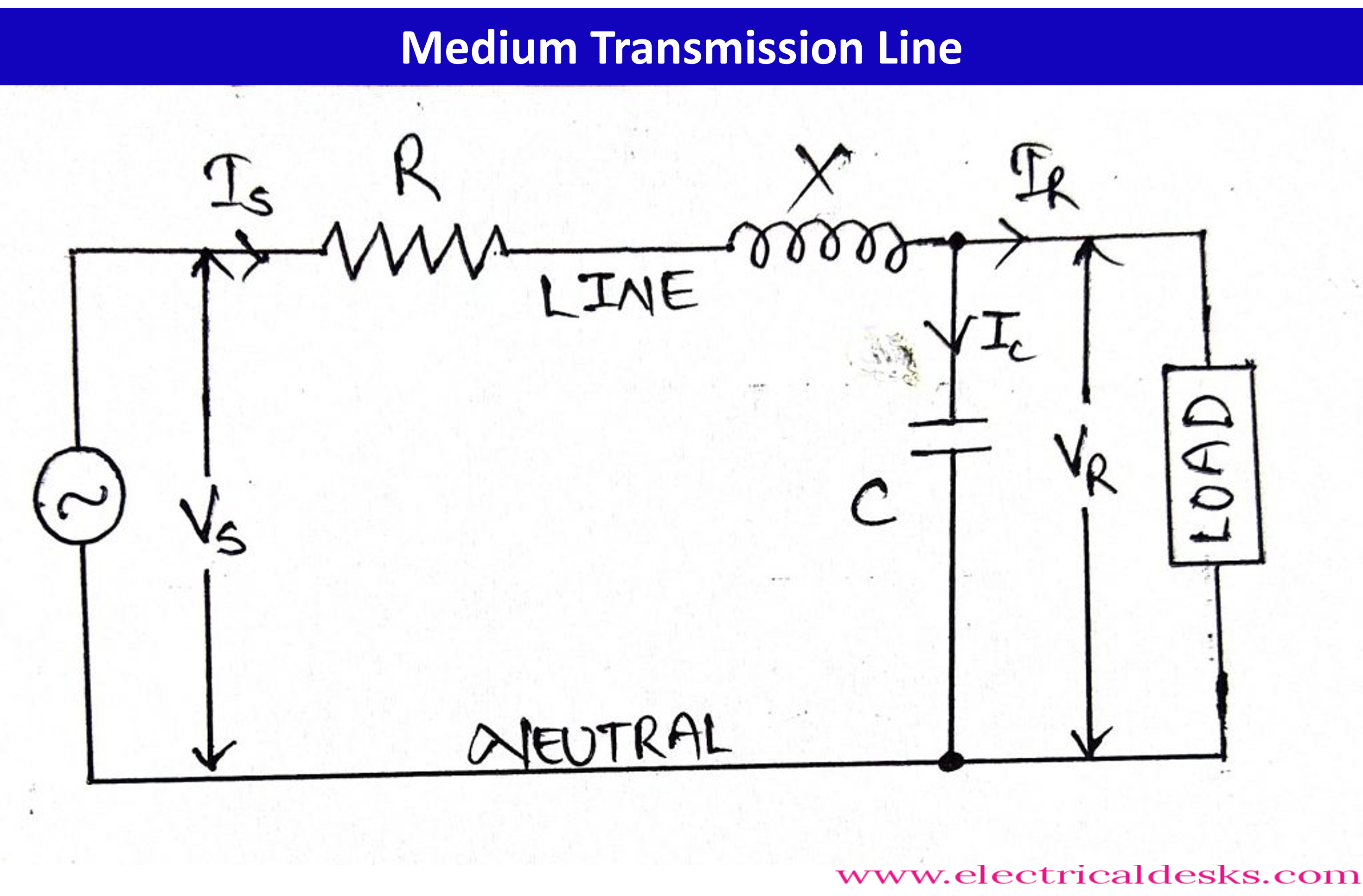
The capacitance of a transmission line forms a shunt element that is distributed throughout the length of the line. This means that the capacitance affects the entire line, not just a specific point on the line. However, for analysis and calculations, it is often assumed that the capacitance is lumped and concentrated at different strategic places along the line. This is done to simplify the calculations and make the analysis of the line more manageable.
Based on the location of the capacitance at different places along the line, medium transmission lines have different configurations. These configurations show the different ways in which the effect of capacitance is taken into consideration in the design and operation of the line. The three main configurations based on the location of capacitance are:
- End condenser representation: In this configuration, the capacitance is assumed to be concentrated at the two ends of the line. This is done to represent the capacitance that is caused by the conductors at the end of the line.
- Nominal-T representation: In this configuration, the capacitance is assumed to be concentrated at two different points along the line, creating a T-shaped distribution of capacitance. This configuration is used to represent the capacitance that is caused by the conductors along the entire length of the line.
- Nominal-π representation: In this configuration, the capacitance is assumed to be concentrated at three different points along the line, creating a π-shaped distribution of capacitance. This configuration is used to represent the capacitance that is caused by the conductors along the entire length of the line.
It is important to note that each configuration has its own advantages and disadvantages, and the choice of configuration will depend on the specific requirements of the transmission line and the goals of the analysis. Engineers will consider the actual placement of the conductors, the voltage level, the line length and other factors while choosing the configurations.
3. Long Transmission Line:
Long transmission lines are overhead power lines that are used to transmit electrical power over a distance of more than 150 km. These lines typically operate at voltage levels greater than 100 kV, and are used for transmitting power over long distances from a generating station to load centers that are located far away.

The treatment of long transmission lines is different from that of short and medium transmission lines, as the length of these lines is greater and the operating voltage is higher. For long transmission lines, the line constants (resistance, inductance, and capacitance) are assumed to be distributed uniformly along the entire length of the line. This is done because the line constants vary continuously along the length of the line and cannot be treated as lumped at a specific point.
Due to the large length and high operating voltage of long transmission lines, the effect of capacitance is significant, and it must be taken into consideration when designing and operating the lines. The capacitance of a transmission line forms a shunt element that is distributed throughout the length of the line. This means that the capacitance affects the entire line, not just a specific point on the line.
To analyze and calculate the performance of long transmission lines, rigorous methods are used. These methods take into account the distributed nature of the line constants and the effect of the environment (such as temperature and weather conditions) on the line. Some of the common methods used for the analysis of long transmission lines include:
-Method of Symmetrical Components
-Method of Characteristics
-Finite Element Method
These methods are more complex and require specialized knowledge and experience to use. However, they allow for a more accurate analysis of the performance of the line and can help identify issues that may not be apparent with simpler methods.
It's important to note that the design, construction and maintenance of long transmission lines are complex tasks and require great care and attention to detail to ensure the safety and reliability of the power transmission. Due to the high voltage and power level on the transmission lines and their remote location, even small faults can cause significant damage and outages, resulting in major financial losses.
2. DC Transmision Line:
DC transmission lines, also known as HVDC (high voltage direct current) transmission lines, are used to transmit electrical power over long distances at higher voltages. The use of DC power for long transmission lines has several advantages over AC transmission lines, including:
- No stability problem: DC transmission lines do not have the stability limits that are associated with AC transmission lines, which can be caused by the interaction between the line's inductive and capacitive reactance.
- Absence of charging current: With DC transmission lines, there is no need to worry about charging current and the resulting losses that are associated with AC transmission lines.
- No skin effect: The skin effect, which causes the current to be concentrated in the outer layers of a conductor, is not present in DC transmission lines.
- No need for reactive compensation: DC transmission lines do not require the same level of reactive compensation as AC transmission lines, reducing the need for additional equipment and lowering costs.
- Bulk power transfer: DC transmission lines can transfer large amounts of power over long distances more efficiently than AC transmission lines.
- Economic power transmission: The use of DC transmission lines can result in lower costs and higher efficiency than AC transmission lines, making them more cost-effective for long-distance transmission.
Despite these advantages, DC transmission systems are not suitable for shorter and medium distance transmission because they need two converters - one at the sending end and the other at the receiving end - to convert the power from AC to DC and back again. The converter at the sending end acts as a rectifier and converts AC to DC, while the converter at the receiving end acts as an inverter and converts DC back to AC. These converters are relatively expensive, and their efficiency reduces as the distance decreases, making the cost of using a DC transmission system for shorter and medium distances not feasible.

It's important to note that HVDC transmission also have limitations such as the cost of the equipment, higher technical complexity and interruption in transmission in case of failure which makes it not ideal for all applications.